STA34
Advanced Multi-Function Programmable Autopilot
Powerful and Adjustable Development Platform
Graphic HMI for Logic and Control Design
High-Precision Measurements Sensor
Semi-Physical Embedded Simulation
High-Speed Data Acquisition
Contents
1. FEATURES ...............................................................................................................................5
2. PURPOSE .................................................................................................................................6
3. PERFORMANCE ......................................................................................................................7
4. MAIN CONNECTOR’S PINS ....................................................................................................8
5. OPERATING PRINCIPLE .......................................................................................................10
5.1. Device Structure ...................................................................................................................10
5.2. Device Functioning ...............................................................................................................11
6. EXAMPLES OF SYSTEM USING ...........................................................................................13
7. MEASURANDS .......................................................................................................................15
7.1. Angles, Accelerations, Angular Velocities ............................................................................16
7.2. Altitude, Climb, Airspeed ......................................................................................................18
7.2.1. Pressures Measurement ...................................................................................................18
7.2.2. Altitude Null Adjustment …….............................................................................................20
7.2.3. Altitude Reset at Certain Point ..........................................................................................20
7.2.4. Null Point Parameters Setting ............................................................................................20
7.2.5. Null- and Airspeed Scale Adjustment ................................................................................21
7.2.6. Airspeed Resetting …….....................................................................................................21
7.2.7. Differential Altitude Measuring Method ..............................................................................21
7.2.8. Restrictions and Recommendations ..................................................................................22
7.3. Magnetic Field Measuring .....................................................................................................22
7.4. Frequency Measuring ...........................................................................................................22
7.4.1. Example of Rotation Rate Measuring ................................................................................23
7.5. Temperature Measurement ..................................................................................................24
7.6. External Voltage Measuring ..................................................................................................25
7.7. Parameters Measured by Built-In GPS-Receiver .................................................................25
8. ConTROL SYSTEM ...............................................................................................................27
8.1. Control System Operation Principle ......................................................................................27
8.2. Control System Units and Their Connection Rules ...............................................................27
8.3. Software for Control System Configurations and Autopilot System Operating …….………..28
8.4. Example of CSC Creating .....................................................................................................29
9. AUTOPILOT SYSTEM ............................................................................................................31
9.1. Autopilot Structure and Operation Principle ..........................................................................31
9.2. Autopilot and Control System Interaction .............................................................................32
9.3. Action of Critical Situations ...................................................................................................34
9.4. Example of Flight Program Creation .....................................................................................34
10. PARAMETERS SAVING .......................................................................................................36
11. INPUT AND OUTPUT PWM SIGNALS .................................................................................37
12. DATA INTERFACE ...............................................................................................................38
12.1. NMEA Protocol Description ................................................................................................38
12.2. ABIP Protocol Description ..................................................................................................38
12.3. RS-232 Interface ................................................................................................................39
12.4. RS-485 Interface ................................................................................................................39
13. LED INDICATORS ................................................................................................................40
14. ERRORS DETECTION .........................................................................................................41
15. USING EXTERNAL CUSTOMER DEVICES .........................................................................42
16. TECHNICAL CHARACTERISTICS …………........................................................................43
17. MECHANICAL CHARACTERISTICS ………….....................................................................44
18. ORDERING INFORMATION ……………...............................................................................45
19. ConTROL LOOP REALIZATION BLOCKS ........................................................................46
19.1. Discrete PID Controller........................................................................................................46
19.2. Summator ...........................................................................................................................49
19.3. PWM Signal Input ...............................................................................................................50
19.4. PWM Signal Output …………..............................................................................................51
19.5. Digital Input .........................................................................................................................52
19.6. Digital Output ………….......................................................................................................53
19.7. Measured Parameter ………………....................................................................................54
19.8. Constant .............................................................................................................................55
19.9. Nonlinear Transformation Block ...............................................................56
19.10. Logical Block …………......................................................................................................59
19.11. Navigation Parameters ………….......................................................................................60
19.12. Angles Difference ………………........................................................................................61
19.13. Comparison ......................................................................................................................62
19.14. Switch ...............................................................................................................................63
19.15. Product .............................................................................................................................64
19.16. Gain ..................................................................................................................................65
19.17. Autopilot Inputs .................................................................................................................66
19.18. Autopilot Outputs ………………........................................................................................67
19.19. Memory Cell .....................................................................................................................68
19.20. PID-Controller Tuning Block .............................................................................................69
19.21. Timer…………… ..............................................................................................................73
19.22. Array Value .......................................................................................................................74
19.23. Flight Navigation Block .....................................................................................................75
19.24. Preprogrammed Function Block .......................................................................................77
19.24.1. Ground Object Coordinates Block ..................................................................................77
19.24.2. Wind Parameters Block ..................................................................................................79
19.25. Transfer Function Block ....................................................................................................80
19.26. Variable Block………………………………................................................................…….81
19.27. Curve Block……………………………………………………………………...……………….82
20. EMBEDDED SCHEMES …………...………………………………………………………..…….83
21. TECHNICAL SUPPORT........................................................................................................85
1. FEATURES
Attitude measurement range: Roll ±180 º, Pitch ± 90º , Heading ±180 º
Triaxial angular rate measurement till 150 º/s
Accelerations measurement range: ±5 g
Altitude measurement till -1000…11000 m
Airspeed measurement till 300 km/h
Internal GPS receiver 5 Hz
Temperature measurement, accuracy ± 3ºC
Processing frequency 50 Hz
Temperature operation range from -25º till + 50º C
RS-232 and RS-485 interfaces
7 Pulse-Width Modulation channels (PWM) (5 V) for servo drives control
6 channels of PWM signals capture (5 V) for signal input from the external control unit
Possibility of external devices connection via RS-485 interface
Configurable control circuits with PID controllers
Till 4 flight programs
Different ways of flight program fulfillment (sequence, interrupt, conditional jumps)
NMEA, ABIP data protocols
User friendly PC software for simple configuration
Power Supply 6V
Power consumption 350 mA
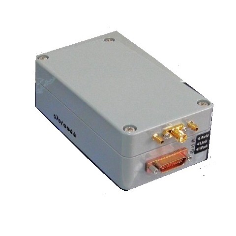
In waterproof case dimensions 115 x 65 x 40 mm
Weight 150g
2. PURPOSE
STA34 UAV Flight Control System is integrated with four major functions - Automatic Control, Data Acquisition, Control Law Design and Semi-Physical Simulation. It can be used as an automatic control device and applied in Fixed-wing Aircraft, Helicopter, VTOL, Car, Boats, Robot and PTZ and Moving Vehicle.
A built-in micro-mechanical inertial block of gauges measures object angular velocities and triaxial angle of attitude. STA34 includes a flexible Control System, which allows user to configure different control loops based on PID control. The System is configured by specific software, which allows constructing of control loops. It is made by junction of basic blocks (inputs, outputs, PID controllers, adders and so on). The software allows also configuring the elements transfer constants.
3. PERFORMANCE
|
Parameter |
Value |
Unit |
|
Roll angle measurement range |
± 180 |
° |
|
Pitch angle measurement range |
± 90 |
° |
|
Heading angle measurement range |
± 180 |
° |
|
Roll and pitch angular resolution |
0.1 |
° |
|
Heading angle angular resolution |
0.3 |
° |
|
Triaxial angular rate measurement range |
± 150 |
°/s |
|
Atmosphere pressure measurement range |
15…115 |
KPa |
|
Differential pressure measurement range |
0…4 |
KPа |
|
Altitude measurement range |
-1000…11000 |
m |
|
Airspeed measurement range |
0..300 |
km/h |
|
Temperature measurement range |
- 20…+70 |
°С |
|
Static pressure accuracy measurement (from 0 till 80ºC) |
± 0.1 |
KPa |
|
Differential pressure accuracy measurement (from 10 till 60ºC) |
± 0.004 |
KPa |
|
Altitude accuracy measurement |
± 10 |
m |
|
Airspeed accuracy measurement (from 10 till 60ºC) |
± 10 |
km/h |
|
Temperature accuracy measurement |
± 3 |
°С |
|
Atmosphere pressure measurement resolution |
0.0033 |
KPa |
|
Differential pressure measurement resolution |
0.0008 |
KPa |
|
Altitude measurement resolution |
0.3 |
m |
|
Airspeed measurement resolution |
2 |
km/h |
|
Climb measurement resolution |
0.25 |
m/s |
|
Processing frequency |
73 |
Hz |
|
Temperature operation range |
- 25…+50 |
°С |
|
Operating voltage |
5.5…6 |
V |
|
Currency |
350 |
mA |
|
RS-232 and RS-485 interfaces baud rate |
4800…115200 |
baud |
|
Dimensions (on case) ( L x W x H ) |
125 х 65 х 40 |
mm |
|
Dimensions (without case) ( L x W x H ) |
104 х 57 х 13 |
mm |
|
Weight in case / without case |
150 / 25 |
g |